Vortex generators are small, but have a disproportionate effect on how your aircraft flies. That’s why it’s important to be careful about how they are placed and maintained.
If it seems counter-intuitive that an aircraft will fly better with little tabs all over its wings, consider the humble golf ball. Vortex generators are to wings what dimples are to golf balls. In both cases the purpose is to delay the phenomenon of airflow separation. For the golf ball, separation creates vortex drag that brings it down to earth long before the green. For the wing, separation leads to a stall.
Vortex generators have become a popular modification for many aircraft. They are available for single and twin engine aeroplanes including the Beechcraft Baron 55 and 58, Twin Bonanza, Cessna 310-320-340 and 402-414-421. They are a particularly useful modification to twins because a properly fitted vortex generator kit lowers the most dangerous number on a twin-engine aircraft: VMCA, the minimum control airspeed (airborne). A twin that falls below VMCA after a critical engine failure can be difficult to recover from the yaw and associated roll that develops. In some applications vortex generators can lower this speed to below clean stall speed, giving the hard-pressed pilot in an engine failure one less thing to worry about.
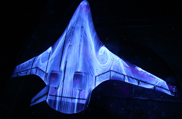
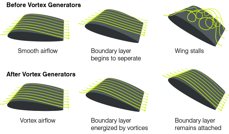
As their name suggests, vortex generators work by re-energising the airstream over an aerofoil. They are usually placed where the airflow starts to loose laminar flow and becomes turbulent. The result is that airflow sticks to the wing better, permitting flight at lower airspeeds with improved control authority.
Vortex generators create a small amount of drag, but this is offset by a cleaner flow of air from the trailing edge of the wing.
All good in theory, and mostly in practice, but like any venture into the world of aerodynamics, detail is critical. Vortex generator kits are tested and certified under supplemental type certificates, and unorthodoxy in their fitting can have unpredictable effects.
Vortex generators how they work
The devil’s in the detail
CASA Airworthiness Bulletin 02-056 of May 2016 discusses the unintended hazards that fitting vortex generators can occasionally bring on. The danger comes when the increased aerodynamic performance that a generator kit allows shows up other flaws in the aircraft’s condition.
The bulletin highlights the possible unsafe conditions that may result from one or any combination of the following:
(a) Subtle wing surface defects upstream of the vortex generator array.
(b) Possible unfavourable interaction between unapproved configurations, or combinations of aerodynamic performance enhancing supplementary type certificate modifications.
(c) An incorrectly configured aircraft, including manufacturer’s boundary layer control devices, i.e. leading edge stall strips, and engine configuration.
CASA received one report about an aircraft that had been modified with a wing vortex generator kit and had not achieved the reduced stall speeds published in the kit’s Flight Manual Supplement. That was disappointing, but worse, the aircraft’s stall handling qualities had been degraded with severe wing drop when approaching the stall.
A thorough examination of the aircraft found a possible explanation. There was an old, unused wing de-ice boot with a leak toward the aft section of its lower surface. When this hole had become exposed to the (new) higher angle of attack, it appears that impact air pressure partially inflated the boot, disturbing the airflow ahead of the vortex generator array. This had resulted in asymmetric stall. Such a hole would have previously gone unnoticed at the lower angles of attack during take-off and landing, before the vortex generator STC was installed.
Not mentioned in the bulletin, but equally instructive, is the case reported in the New Zealand CAA’s Vector magazine of the operator of a Piper PA31 Chieftain that had a vortex generator kit installed on the fin—and a vinyl decal applied over the generators.
AWB 02-056 adds another, often overlooked caution: aircraft manufacturer’s maintenance inspection schedules are designed for unmodified aeroplanes.
If your aircraft has been modified to alter its design, gross weight or performance, you may need have it inspected more frequently, or even impose a reduced fatigue/retirement life.
The reason why is that with better performance and/or higher gross weight the aircraft is working harder, with more stress on its spars, engine and other structural components. Vortex generators and other aerodynamic kits certainly liberate extra aircraft performance, but in aviation, as in life, nothing comes for free.
Examples of common STCs not covered by manufacturer’s maintenance schedules include wing extensions, winglets, speed brakes, short take-off and landing (STOL) conversions, under-wing and wing-tip tanks, external cargo pods and non-standard engines, as well as vortex generators.
AWB 02-056 goes on to discuss stall strips; unlike vortex generators these add-ons slightly degrade the aircraft’s stall resistance, but do so in a way that, when properly fitted, makes a stall less likely to result in wing drop or other loss of control. Stall strips usually produce a more pronounced stall buffet, giving extra warning to the pilot that the aircraft is at high angle-of-attack.


The same general principles apply to keeping stall strip installations safe. Over an aircraft’s service life it is very important to ensure that stall strips stay correctly fitted, are not damaged, and are not compromised by other equipment that may be fitted to the aircraft unless the aerodynamic implications have been assessed.
AWB-02-056 makes the following recommendations. Because an aircraft may have wing asymmetries or configuration problems which may only become evident during flight at slow speeds and the higher angles of attack achievable with vortex generators installed, CASA recommends that:
(a) Devices such as de-ice boots (if installed) are carefully inspected for damage and as a possible source of wing asymmetry.
(b) Any wing or flying surface damage has been carefully and accurately repaired. Check both wings have the same or specified washout (twist) from wing root to tip, for example.
(c) The configuration of any wing leading edge stall strips is strictly in accordance with the manufacturer’s data, or as required by, or in conjunction with, the applicable STC(s).
(d) The aircraft flight control surface rigging and engine configuration is that which will provide the highest safety margins.
(e) The interaction and possible conflict between various STCs, modifications and aircraft manufacturers service letter installation requirements, are carefully assessed and resolved before operating a modified or de-modified aircraft.
(f) The aircraft owner and/or maintenance organisation should contact the STC holder(s) or modification originator to obtain the approved inspection data.
(g) Suitably qualified personnel should carefully and properly investigate all aircraft configuration irregularities, and/or any suggestion of anomalous flight characteristics following a repair, or the installation of an STC, or approved modification involving any form of aerodynamic or performance enhancement.
