Mast bumping is an instant terminator of helicopter flight, and pilots’ lives. It needs to be understood to be avoided.
Case study: tested to destruction
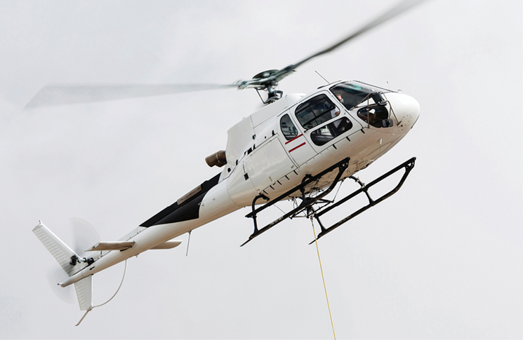
A series of flight tests was being conducted to certify a new rotor blade design on a Bell 206 helicopter. This was to be the last flight gathering the required data before the certification could be completed.
The blades were fitted with strain gauges and aircraft performance parameters were also recorded. The flight consisted of a series of autorotations at high weight. The pilot would wind off the throttle and allow a one-second delay before adjusting the controls for autorotative flight. (The one-second delay is used in certification standards to allow for average pilot reaction time.)
The helicopter was crewed by a commercially rated pilot with 1,200 hours and a flight test engineer who had some flying experience. The engineer would direct the sortie through the series of tests, using a clipboard for reference while also operating an instrumentation system to record the blade stresses and helicopter performance parameters.
The engineer sat at the copilot’s seat and normal company policy stated the dual controls would be removed. In this case the dual controls were still installed. The engineer had to juggle a clipboard, a laptop weighing 3.5 kg and a corded, event marker button.
All of this had to be managed during the dynamic autorotational sequences while trying to keep them clear of the dual cyclic controls. The engineer was busy with a high workload and it was postulated that this crewmember had to hold the laptop above the dual cyclic controls while trying to operate it.
One sortie had successfully been conducted, at Fort McDowell in Arizona, USA, in April 2019, and the aircraft landed to take on ballast to offset the fuel burnt. A series of simulated engine failures, entry to autorotation and manoeuvres in autorotation were then conducted over about 30 minutes.
The aircraft was at about 3,000 feet AGL when a witness on the ground heard a large bang and observed the helicopter falling vertically to the ground. The main rotor and empennage separated from the helicopter and landed separately to the fuselage. The accident was not survivable and both occupants died.
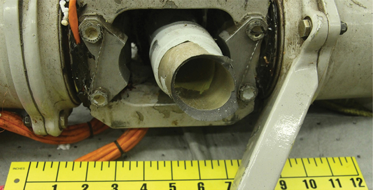
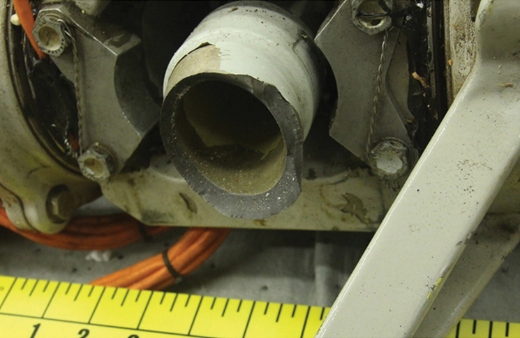
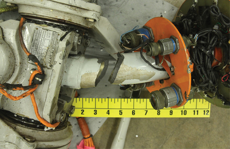
The FAA accident report identified there were witness marks on the rotor blade from either the tail boom or tail rotor, indicating the blades were flapping widely. The rotor head was found intact, with the mast separated 1/5 to 2 inches below the static stops.
The main rotor mast had witness marks from the hub of the teetering rotor head striking the static stops. This indicated that mast bumping is likely to have occurred, causing the rotor to separate from the aircraft and the main rotors to chop off the empennage.
The entry to autorotation would have resulted in a transient load of less than 1G on the aircraft. It was suggested the engineer possibly knocked or interfered with the cyclic at the moment of entry to autorotation, causing severe mast bumping and leading to separation of the main rotor.
Rotor dynamics and designs
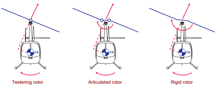
The Bell 206 rotor head design is called semi-rigid teetering as the 2 blades are joined to a rigid hub which is attached to the mast by a central pivot. This allows the rotor disc to tilt, allowing the helicopter to be manoeuvred. Helicopters with semi-rigid teetering rotor heads include the Robinson R22, R44 and R66, Bell 206, Bell UH-1 Huey and Bell 505.
In contrast, articulated rotors have a fixed hub attached to the mast, and hinges offset from the mast centre line to allow blade flapping. A third type of rotor is rigid (or, strictly speaking semi-rigid). These rotors have a fixed hub attached to the mast. Blade flapping is achieved by flexing of the rotor blades further out from the mast centre line. The Westland Lynx uses such a design. In articulated and rigid rotors, the hub is fixed to the mast and cannot move; in the teetering design, the hub can move at the central pivot point on top of the mast.
These rotor head designs allow the rotor disc to be tilted and the helicopter manoeuvred. In the teetering design, the lift vector is tilted – this sets up a moment around the CoG to tilt the fuselage. In an articulated rotor, there is an additional moment set up due to the forces acting about the mast from the fixed hub.
For articulated and rigid rotors, this means there is a combination of a moment at the rotor hub and the moment about the CoG. This generates more control power to manoeuvre the helicopter.
Finally, in a rigid rotor, the virtual hinge is even further out from the hub and you get an even greater turning moment at the hub, combining with the moment about the CoG, generating even more control power.
In the case of the teetering head, if the helicopter is subjected to low, zero or negative G, a sufficient moment about the CoG cannot be generated due to the reduced helicopter apparent mass; the aircraft fuselage flops around relative to the rotor hub.
The tail rotor is also still producing some level of force and this can further roll the helicopter fuselage, so the rotor blades reach a dangerous flapped position with respect to the mast and tail boom.
In the case of articulated or rigid rotors during low G, the moment generated in the fixed hub acts to keep the fuselage orientated to the rotor.
Analysis
Entry to autorotation in teetering rotors occurs all the time for basic flying training. The testing of new rotor blades should not of their own have caused problems sufficient to cause this accident.
In this case the engineer was trying to juggle several items in this cockpit above the cyclic. It was postulated by the FAA that, had the engineer bumped the cyclic accidentally at the moment low G was being experienced, it is likely the fuselage could not follow the rotor hub tilt, and mast bumping and excessive blade flapping occurred.
If the engineer had bumped the cyclic forward, this would have further exacerbated the low-G situation. Unfortunately, the flight test instrumentation recording of the accident was not able to be recovered to conclusively prove this proposition.
What equipment aircrew take into a cockpit needs to be carefully considered. Not fouling the controls should be an obvious priority. Conducting flight tests or non-standard operations requires some form of risk assessment. Being reasonably informed of what risks there are may require some lateral thought.
Although a laptop computer is not normally used in the cockpit, similar devices such as electronic flight bags (EFB) are. EFBs are common tablet devices pilots take into the cockpit, to provide information and decrease workload. Considering operational guidance may have helped prevent this accident. CASA Advisory Circulars (AC) provide guidance on taking an electronic device into a cockpit safely. AC 91-17 v1.3 includes comments, such as:
The size of the proposed EFB may make it cumbersome during normal use. A laptop may have sufficient computing power to handle the required software, but the size may be a hindrance. It is possible to have an EFB that is handheld. In this case, the operator may impose restrictions on its use, such as requiring the device to be stowed during critical phases of flight. EFB systems that are not secured in a mounting device during use must be designed and used in a manner that prevents the device from jamming flight controls.
It would not be unreasonable for a flight test program to consider ACs like this to ensure they are reasonably informed about the risks that may be present. If it was a requirement to have the dual controls to meet a flight control system test point, then the laptop should have been more appropriately secured or the engineer should have been in the back seat.
If dual controls were not required for the test, they should have been removed. This may seem obvious but, in this accident, an oversight or a shortcut allowed the engineer, laptop and the dual cyclic controls to be in the same place at the same time, with a tragic results.
For those considering conducting flight tests, CASA provides further guidance on safe conduct and setting up a safe flight test activity, in AC 21-47 – Flight test safety.
Teetering rotor helicopters must not be exposed to low-G situations – a healthy buffer from this phenomena is good practice. In normal flight operations, low G may be experienced when bunting over a ridge line, in rapid descent to avoid a bird, mishandled wingover manoeuvres or turbulence. Pilots should fly to avoid low G in teetering rotor head helicopters.
Avoidance
What to do though if a pilot finds themselves approaching or in a low-G situation?
If turbulence is encountered when slowing down, avoid abrupt flight control inputs and comply with the flight manual restrictions or turbulence penetration speed. Having an option to turn around or land and remove the helicopter from turbulence is a wise policy.
On some days it may be better to stay on the ground. In December 2020, a R44 helicopter (teetering rotor head design) broke up in flight near Goulburn due to mast bumping and turbulence.
If the helicopter is mishandled and the pilot finds themselves approaching low G, the aim is to re-establish positive G. This is best done by moving the cyclic aft before correcting any excessive roll. Tail rotor thrust can roll the aircraft in an unload situation. It is important that positive G is re-established before any correction to the roll is attempted. Applying a roll correction before establishing positive G will only cause further excessive flapping and reduce the margins from catastrophic mast bumping.
Conclusions
Flying of teetering helicopters is not inherently unsafe if operated in accordance with their flight manual limits. However, sometimes pilots may find themselves in unusual situations, where a greater understanding of why these limits exist will allow better forecasting of risk.
As with all accidents, there are several holes in the Swiss cheese model that lined up in this case to contribute to the result:
- Why were the dual controls left in?
- Why wasn’t there a better set-up for the engineer’s instrumentation suite?
- Could the engineer have performed their duties from the back seat, if dual controls were required to represent a complete control run?
Just because you are doing something different doesn’t mean that guidance material for normal operations isn’t still relevant. Testing to destruction was never the aim of this flight; however, thinking that the operations were different and did not require normal aviation safe practices, led to a destructive outcome.
Read the full accident report at the National Transportation Safety Board.


Comments are closed.